Gas chlorination for the upgrade of two drinking water plants
I am designing a gas chlorination system for the upgrade of plants built in the 1970s–80s. Each plant treats over 15,000 m³/h.
Input data
| Capacity of each plant | over 15,000 m³/h |
|---|---|
| Reagent | liquid chlorine in 1 t containers |
| My role | process engineer: calculations, equipment selection, P&ID, specification, safety section, scrubbers for both plants, control logic; then installation supervision and commissioning |
Engineering challenge
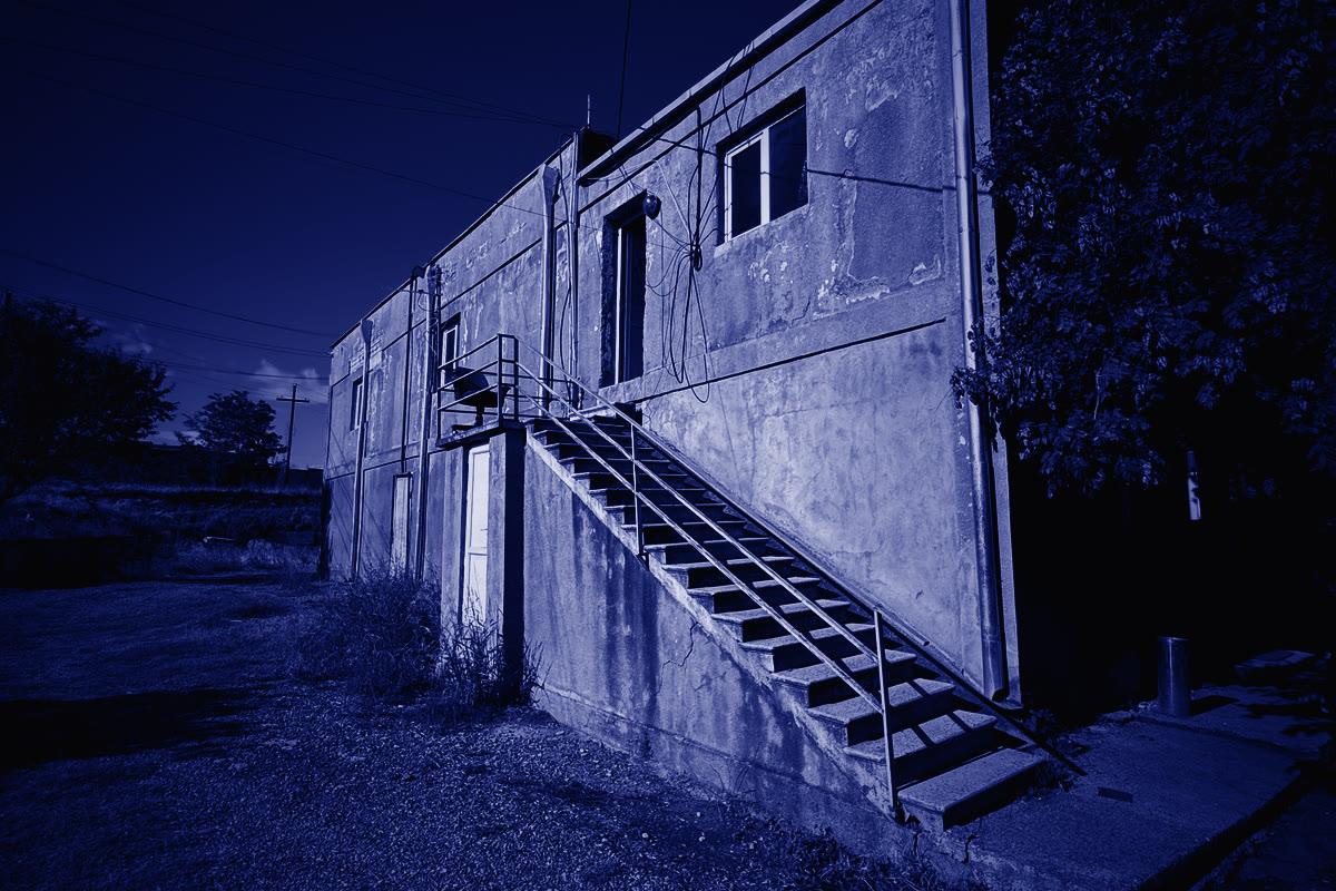
The plants were built in the 1970s–80s, and the chlorine system has to be replaced. The new system must hold the set dose accurately, leave headroom for capacity growth and stay safe along the whole chlorine path, from storage to injection into the water.
Solution
A vacuum gas chlorination system with standby at every stage, from the container store to the ejectors at the injection points. The diagram below shows how it works.
Result
| P&ID | issued for both plants |
|---|---|
| 3D model, process, architectural and electrical design | complete for the first plant |
| Automation | developed for the first plant |
| First plant installation | early 2027 |
The solution step by step: chlorine path from storage to water
- 01
Storage
1 t containers
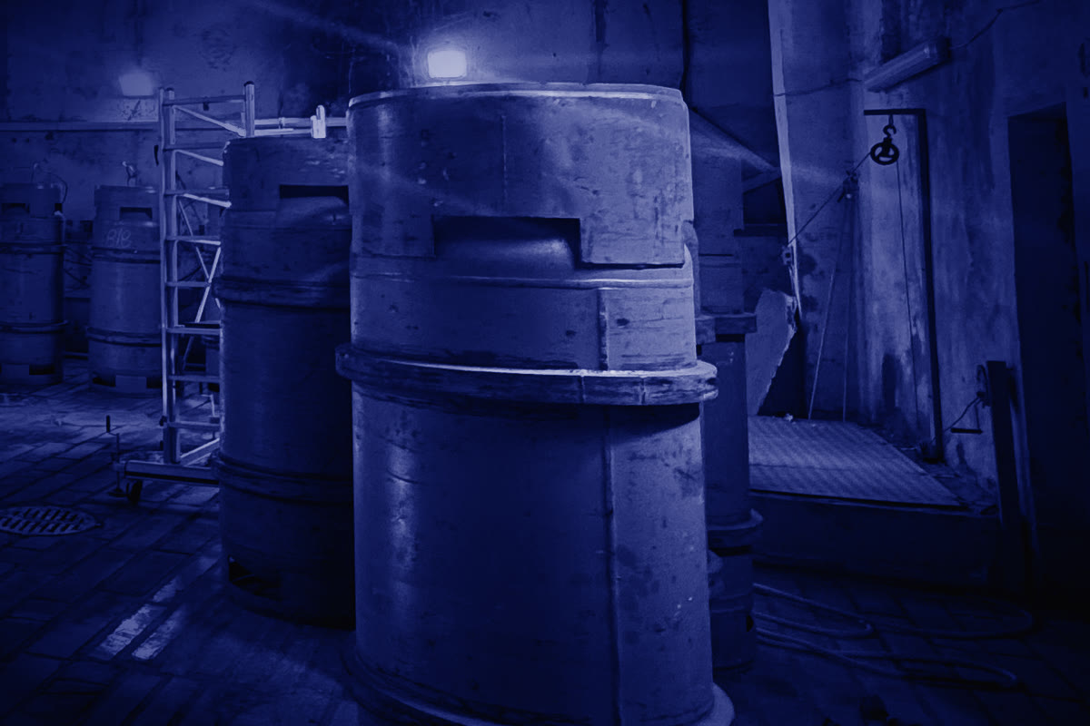
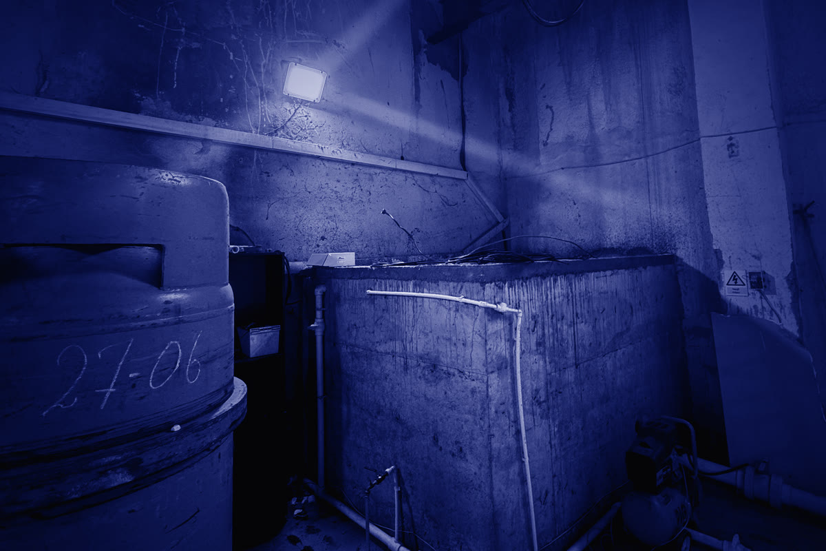
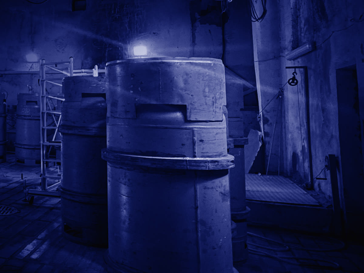
Two container racks on scales with automatic changeover. Stock sized for operation at maximum dose.
- 02
Liquid chlorine feed
liquid phase
Seamless steel piping, motorised valves and pressure monitoring. Overpressure protection on the lines.
- 03
Vaporisation and pressure reduction
duty + standby
Electric vaporisers, gas filter, pressure reducing and relief valves.
- 04
Vacuum dosing
under vacuum
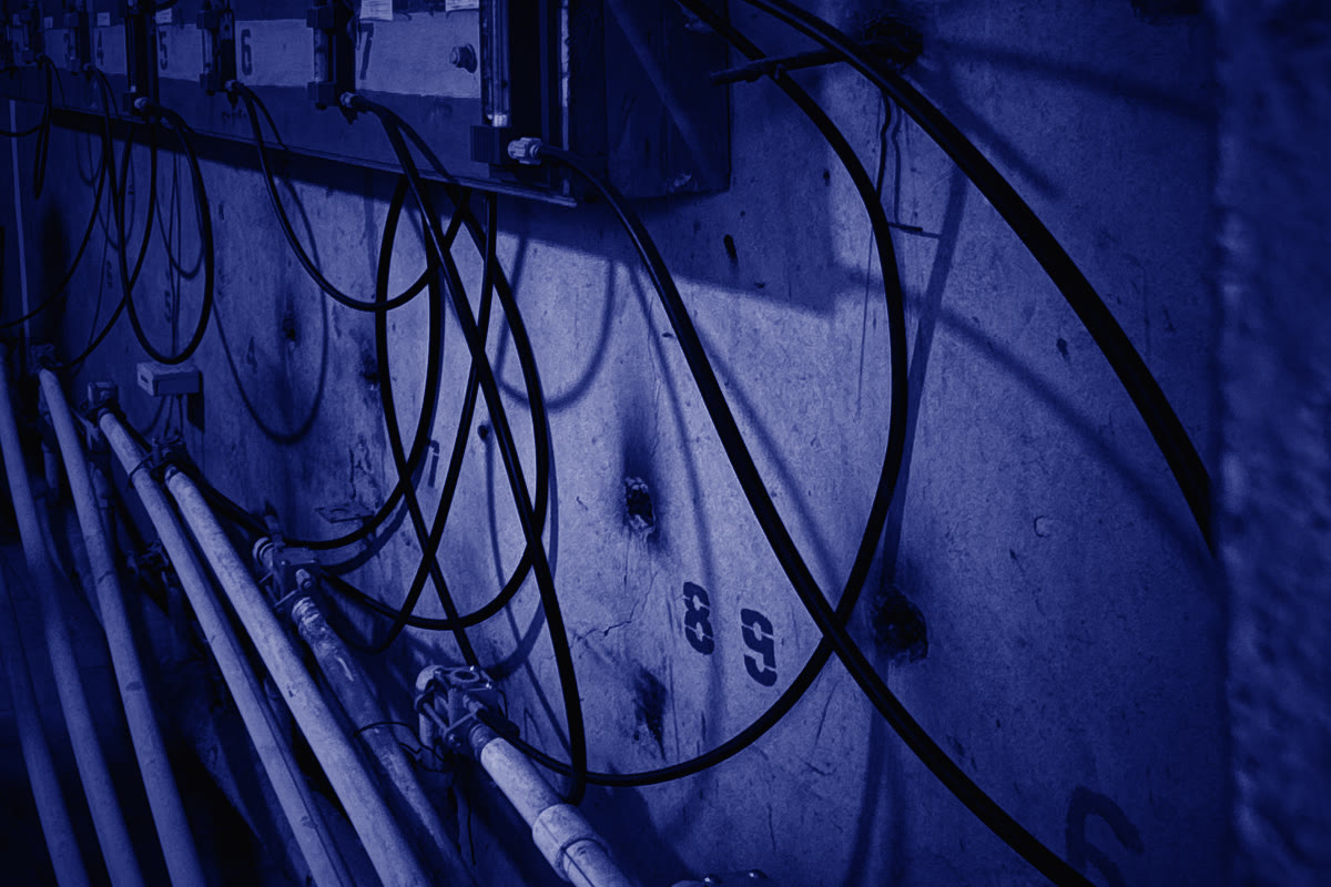
Vacuum regulators with standby and shut-off on vacuum loss. Chlorinators dose in proportion to water flow.
- 05
Ejection and injection
on motive water
Ejectors, a flowmeter and check valves on every line. Injection for pre-oxidation and disinfection.
Safety
Chlorine leak detectors, audible and visual alarms. Automatic emergency shut-off of the containers on a signal from a detector, button, SCADA or fire alarm. Scrubbers neutralise chlorine releases.
Control
A local PLC with an operator panel linked to the plant PLC. The dose is paced by water flow; residual chlorine is measured continuously.
My role
Process calculations, equipment selection, P&ID, specification, safety section, scrubber design for both plants. Supervision of the 3D model and layout, control logic for the programmers and its review.
On site